
Engineering Scale Models: 3D Printing Bridges, Roads and Plants
Six engineering and infrastructure scale models from PrototypeBD's workshop, from a 4 ft highway interchange for RHD to a 1:2 engine, and what they show about scale, splitting and finishing.
Many scale models are buildings. Some of the most interesting ones are not: a highway interchange, a river bridge, a tugboat, a concrete batching plant, a pair of power-line towers and a half-size racing engine. An engineering scale model exists to show how something connects, carries load or works, so a 3D printed one runs into problems an architectural model never has. A lane or a truss member shrinks below what a printer can draw. A site board is several times wider than any print bed. And the finish has to read as asphalt, steel or water from across a meeting room.
This case study walks through six engineering and infrastructure models from PrototypeBD's Facebook posts between 2022 and 2026. It covers what each one shows, and the three things they taught us about accuracy versus scale, splitting large models and finishing. Where a post names the client or the designer, we credit them.
In short: An engineering scale model is a smaller copy of a bridge, road, plant or machine that shows how it connects or works. With FDM 3D printing the limits are millimetres, not scale: walls under about 0.8 mm don't print, and anything over the bed size is printed in parts and joined.
Six models from the workshop
1. Hatikumrul Interchange, four versions
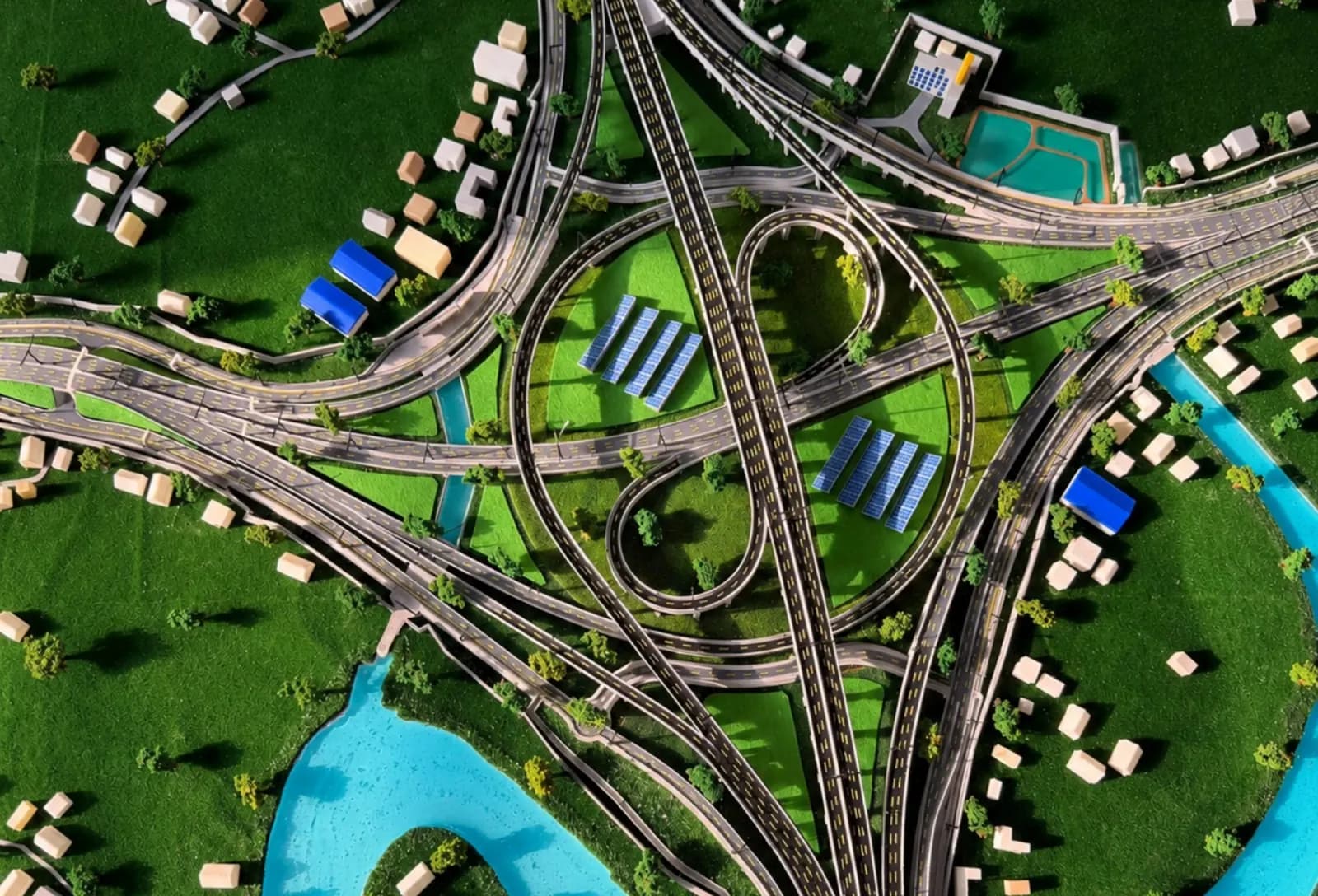
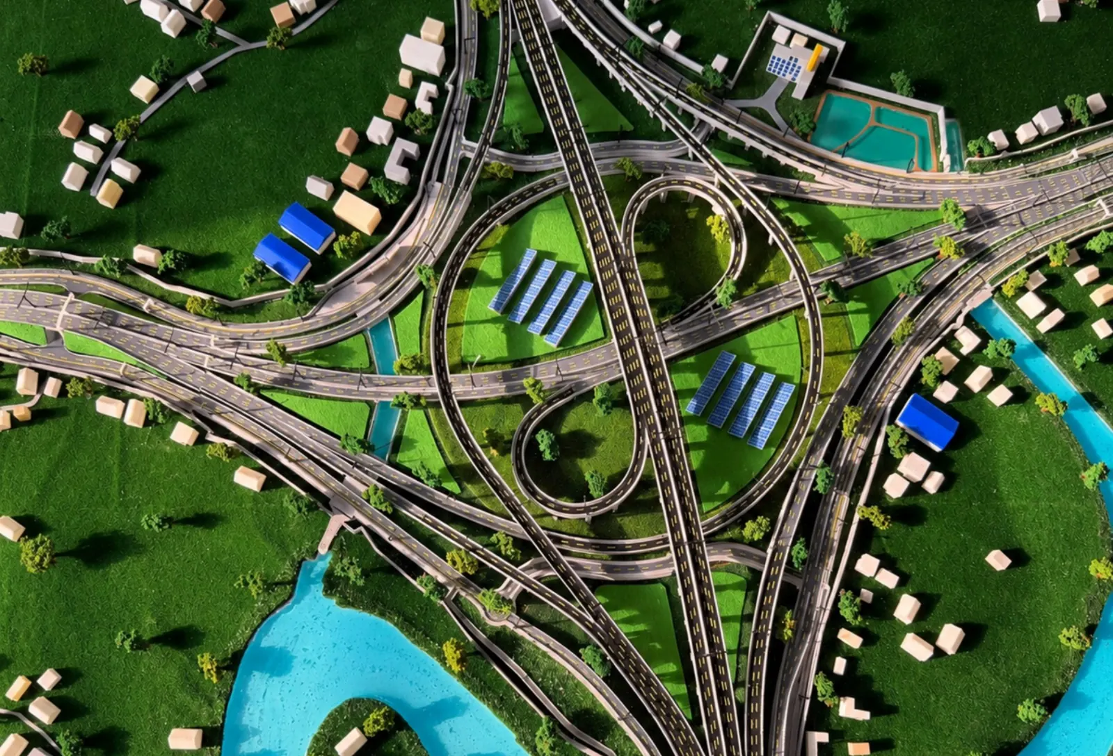
Hatikumrul, in Sirajganj, is a large cloverleaf-type interchange where the routes from Dhaka towards Rajshahi, Pabna and Rangpur meet. It is part of the SASEC Dhaka–Northwest Corridor road project. We have modelled it more than once. The December 2025 plaques and the September 2026 presentation model were both made for the Roads and Highways Department (RHD), Bangladesh, as the posts say:
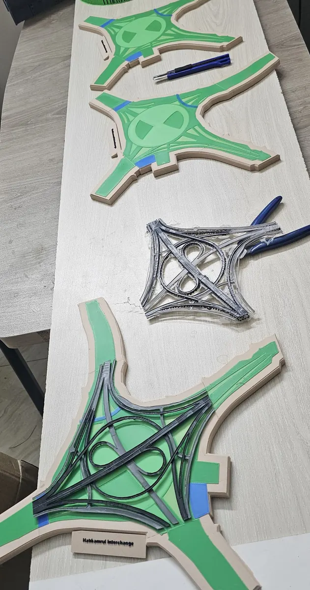
- February 2025, desk-size models, made in several copies. PrototypeBD made the 3D design, printed them and assembled them. The photos show green base pieces with a tan edge, a grey road network printed as a separate part and a small name plate.
- October 2025, landscape version. Shown on yellow display bases, one of them under a clear cover. The post describes capturing elevation and contour data in the print.
- December 2025, a batch of round plaques. A large batch of identical round interchange plaques, photographed together before delivery. They are a small, repeatable version of the same road layout.
- September 2026, a 4 ft × 4 ft presentation model. We handled every stage: 3D design, printing, crafting, painting, detailing, landscaping and final assembly. The model shows the road network, elevated sections and ramps, surrounding structures, water bodies and landscape.
2. Padma Bridge miniature
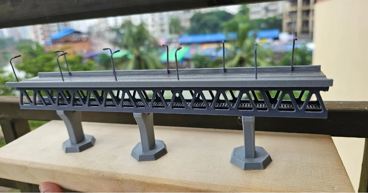
The real Padma Bridge is a 6.15 km, two-level steel truss bridge with 41 spans of about 150 m. A four-lane road runs on top and a railway runs below. Our miniature, which we designed, printed and assembled in 2025 for Valiant Tigers, shows a short section of it: the road deck with lamp posts, the lattice truss underneath and three tapered piers.
3. A tugboat
A scale tugboat in blue, red and white, with deck fittings, railings, fenders and a mast. It sits on a polished display base. The tugboat is a client design: the client supplied the design and PrototypeBD 3D printed it.
4. A concrete batching plant
The model shows three blue-and-white silos on lattice legs, yellow feed pipes, the mixing platform with stairs, an inclined conveyor and a site cabin. It was 3D printed and then assembled by hand.
5. A 1:2 flat-12 engine
In October 2024 we printed a half-size model of the Porsche 917's twelve-cylinder racing engine. It is a client design: the client designed the model, and PrototypeBD 3D printed it. The real engine, the Type 912, is a 180° flat-12. Its cooling fan is large and mounted horizontally on top, driven by gears from the middle of the engine (Wikipedia: Porsche 917). The model shows the same layout: two banks of finned cylinders, the fan housing on top, a gear at one end and a red hand crank. The post describes it as fully functional.
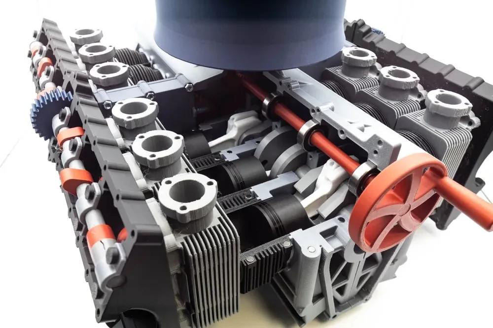
At half size the problem is no longer detail but fit, which we come back to in the accuracy section below.
6. Transmission line towers
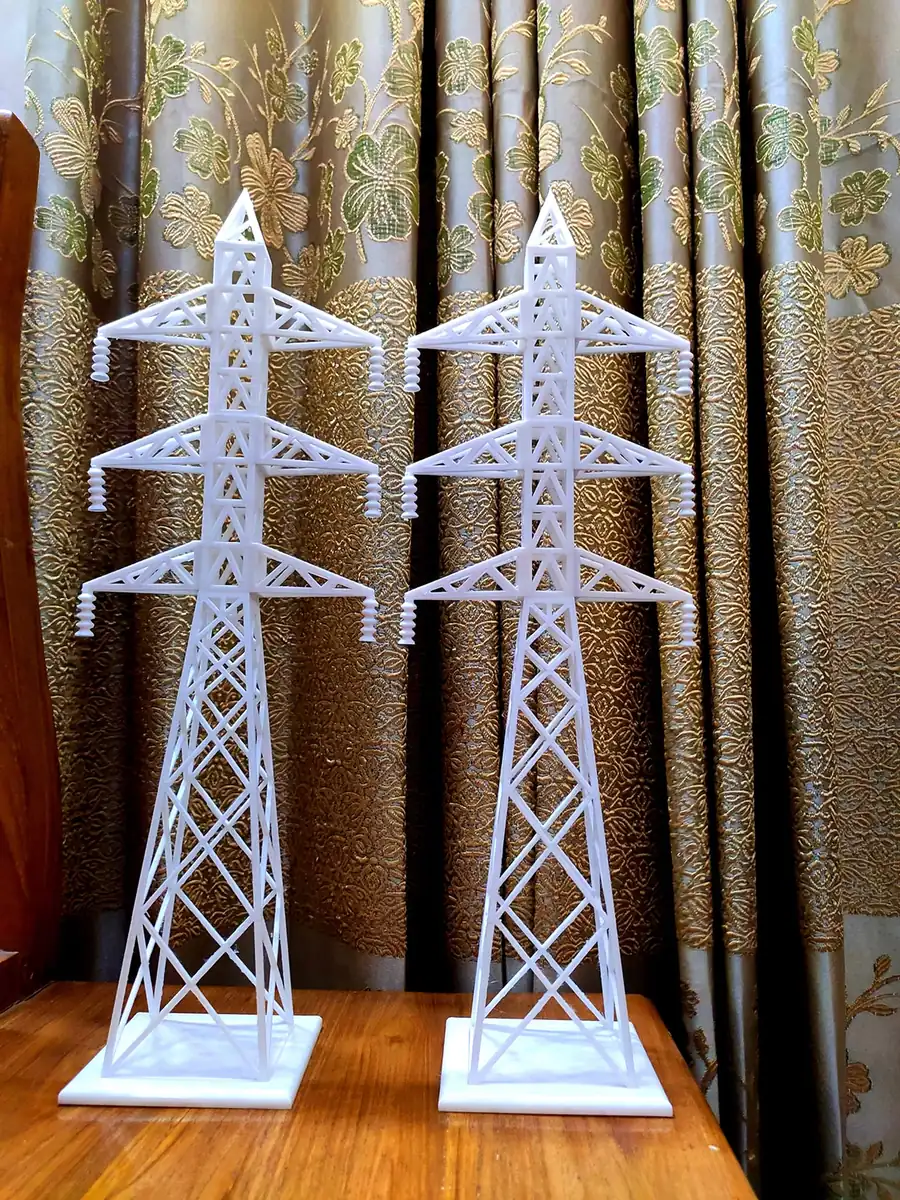
In 2022 we printed two lattice transmission towers for a student project on three-phase fault detection in transmission lines. They are white, with three cross-arms each and insulator strings at the arm tips.
Oil and gas plant models are a separate topic. We cover them in 3D printed oil and gas equipment models.
Accuracy versus scale: what a printer can actually draw
A printer does not care what scale you chose. It cares how thick each feature is in millimetres. A typical FDM wall needs to be about two to three times the nozzle diameter, roughly 0.8 to 1.2 mm. Fine features in the horizontal plane are limited by the 0.4–0.5 mm nozzle. Turn that around and you can see which real details survive at a given scale. Our architectural model guide covers the same limit for buildings; here it is for infrastructure:
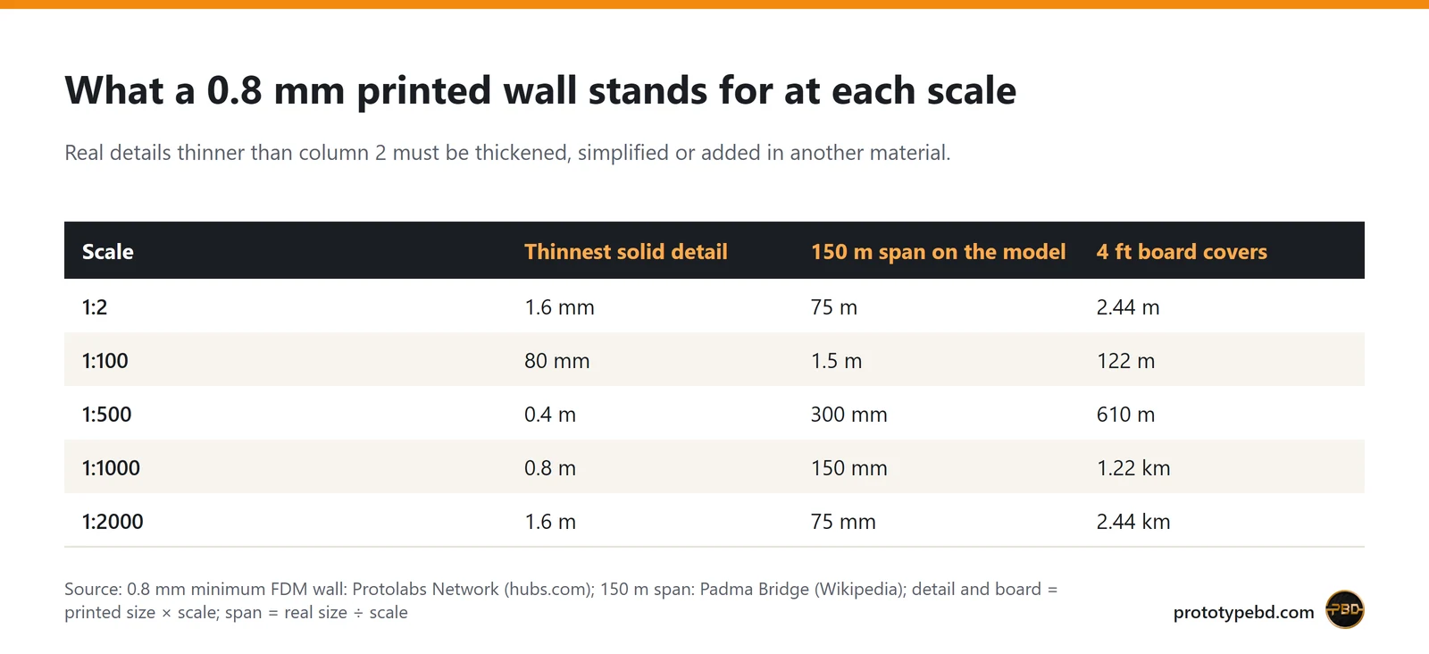
| Scale | Thinnest solid detail | 150 m span on the model | 4 ft board covers |
|---|---|---|---|
| 1:2 | 1.6 mm | 75 m | 2.44 m |
| 1:100 | 80 mm | 1.5 m | 122 m |
| 1:500 | 0.4 m | 300 mm | 610 m |
| 1:1000 | 0.8 m | 150 mm | 1.22 km |
| 1:2000 | 1.6 m | 75 mm | 2.44 km |
What this means for the models above:
- Site-scale models (interchanges, corridors). At site scales such as 1:1000, where a 4 ft board covers about 1.2 km of ground, anything thinner than 0.8 m in real life is below one printed wall, and that includes guard rails, lamp posts, lane markings and thin bridge parapets. Those details are thickened on purpose, painted on or left out. That is a design decision, not a printing fault, and it should be agreed before printing.
- Lattice structures (truss bridges, towers). On a desk-size lattice, true-scale members would be thinner than 0.8 mm, so they are drawn thicker. A printable lattice keeps the pattern and the proportions of the bays, with members drawn thicker than true scale. Ask for the pattern to be readable, not for the members to be exact.
- Machine models at large scales, like the 1:2 engine. At half size nearly every real feature is thicker than a printed wall, so the limit moves from detail to fit. Our FDM quote page gives a typical tolerance of about ±0.2 mm and warns that holes usually print undersize. Shafts, gears and cranks that must turn need clearance designed into the file, and some holes need drilling or reaming. For a crank or piston that has to turn by hand, PrototypeBD starts from 0.1 mm between moving faces and opens it up to as much as 0.3 mm, depending on the filament and the machine. Mark in the file which parts must move.
Splitting large models into printable parts
The beds listed on our FDM 3D printing quote page run from 256 mm (Bambu Lab A1) to 330 × 320 mm (Bambu Lab A2L) and 400 × 400 × 400 mm on the large-format machines. For a site model, even the biggest machine in the workshop falls short: a Creality Ender-5 Max with a 400 × 400 × 400 mm build volume (Creality) covers only a third of one side of a 4 ft board, which is 1219 mm. The smaller pieces, such as ramps, piers and buildings, go on the Bambu Lab P1S, P2S and X2D printers (X2D launch release) that do most of PrototypeBD's work.
So any engineering model bigger than a desk plaque is a kit of parts. Three habits help hide the joins:
- Split by layer before splitting by area. The 2025 interchange photos show the base and the road network as separate prints. Each layer can then be printed in its own colour, which can also limit supports to the upper layer.
- Cut where the real structure has a joint. Pier lines, expansion joints, road edges, the line between a silo and its legs, or the edge of a water body. A seam along a real line reads as detail. A seam across a lawn reads as a crack.
- Key the parts together. Slicer cut tools such as PrusaSlicer's cut tool add plugs, dowels or dovetails so pieces only fit one way; our high-rise model guide covers where to split in more detail.
A standard order through the quote page delivers oversized parts in sections for you to join. The assembled models in this article, like the 4 ft interchange, were custom jobs where we also designed, assembled and finished them. On a site board, the extras that make it read as a real place, such as painted water, scale trees and figures or LED street lighting, can be added on request together with assembly. They are quoted job by job rather than included in a print price.
Finishing: what makes a print read as steel, water or asphalt
Raw FDM parts show layer lines, and a presentation model is usually seen from close up. A quote-page print arrives with supports removed and surfaces cleaned. Sanding, priming and painting are not included. For a presentation model there are two routes:
- Print in colour. Parts printed in the final filament colour, as the green, tan and grey layers of the 2025 interchange appear to be. This is quick, and edges stay crisp, but layer lines stay visible.
- Prime and paint. The usual method is to sand, apply a filler primer that fills layer lines, sand again and paint in thin coats. Heavy filling softens fine edges, so it suits hulls and silos better than lattice towers. The 2026 interchange went further, with painting, detailing and landscaping (water, trees, buildings) added by hand after printing.
Decide which route you want before the quote, because it changes the schedule and the price.
What to send for an engineering model quote
- Files. STL, 3MF and OBJ get an automatic sliced price on the FDM quote page. STEP and STP files are accepted and priced by hand. If you only have drawings, a site plan or photos, our CAD design service can build the 3D model first.
- Target size or scale. Give one of them and we work out the other. Say which details must stay readable at that scale, such as ramp levels, truss pattern, silo count or moving parts.
- Purpose. A presentation model, a teaching aid or a working mechanism each lead to different wall thicknesses and clearances.
- Finish and deadline. Bare prints usually ship within 2–5 working days of confirming the quote. Multi-part orders and very large pieces take longer, and painted, assembled models need their own schedule.
For very small, sharp parts such as railings, figures or tiny fittings, a resin print can hold more detail than FDM. See SLA resin printing.
Related articles
Product prototyping with 3D printing: real examples from Bangladesh
Why to prototype before tooling, what form, fit and function prototypes test, and how tight printed fits can be, with eight projects from our Dhaka workshop.
3D Printed Enclosures for Electronics in Bangladesh: Eight Projects and the Design Rules
Eight electronics enclosures PrototypeBD designed or printed, from an IoT gas meter to an MPPT charge controller, and the wall, boss, vent and material rules they show.
3D Printed Robot Parts in Bangladesh: Six Robotics Projects and a Display Model
What PrototypeBD's robotic arm, rover, self-balancing robot, drone and gear-model prints show about orientation, gears, shafts and filament choice for student robotics.
Comments
Loading comments…