
3D Printed Oil and Gas Equipment Models: From CAD to Print
Three palm-sized oil and gas equipment models that PrototypeBD designed in CAD and 3D printed, one of them for a Sylhet client, and what to send if you need one.
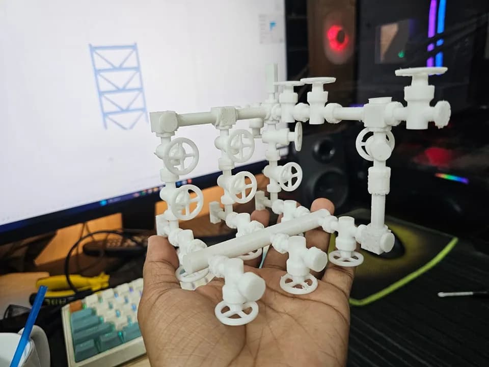
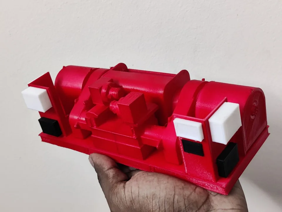
In one week of June 2024, PrototypeBD posted three 3D printed oil and gas equipment models: a choke manifold, a crown block and a red rig-machinery model. Each one was modelled in CAD by the PrototypeBD team and then 3D printed by PrototypeBD. None of them is a working part. They are scale models that fit in one hand, and that is what makes them useful. The red rig model was made for an oil and gas client based in Sylhet. This case study shows what was made, what the photos tell us about the process, and what you should send if you need a similar model.
In short: these are hand-sized display models, not working equipment. Each one is modelled in CAD at full size, scaled down, checked against FDM limits (about 2 mm for small features and 0.8 mm for walls), printed in sections and assembled. To order one, send photos or drawings, the main dimensions, the scale you want and what the model is for.
The three models
Choke manifold
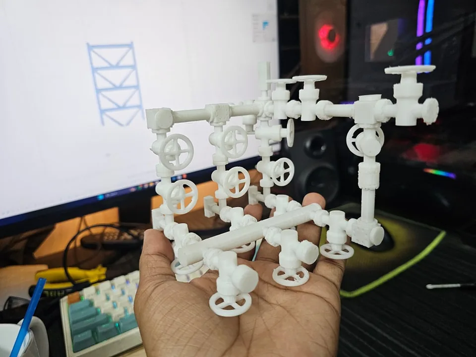
On a drilling rig, a choke manifold is a group of high-pressure valves and pipes with at least two adjustable chokes. One choke can be shut off for repair while the flow goes through the other (SLB Energy Glossary). The model shows that layout as a frame of vertical pipe runs, a horizontal header and more than a dozen valves, each with its own spoked handwheel. The post shows two prints of it, one in red and one in white.
The white print is a good example of how much detail a palm-sized FDM model can carry, and where it stops. The handwheels and valve bodies are clear, but the photo also shows small blemishes on the pipe runs. Up close, an FDM model looks like a model, not a cast miniature.
Crown block
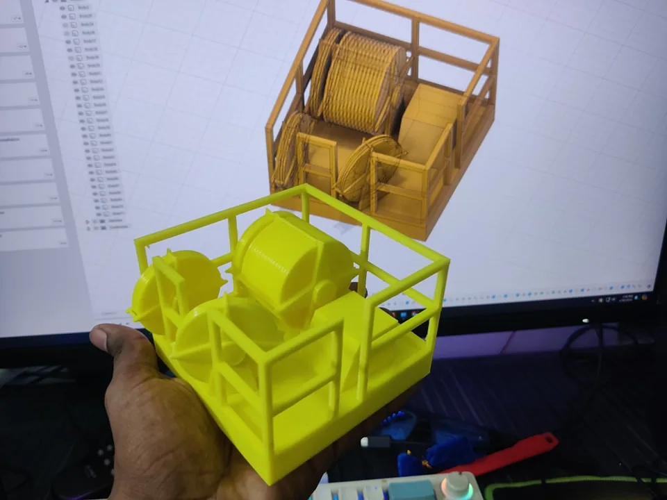
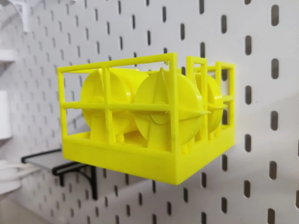
A crown block is the fixed set of pulleys, called sheaves, at the top of a derrick or mast. The drilling line runs over these sheaves and down to the travelling block, which gives the rig a large mechanical advantage when it lifts the drill string (SLB Energy Glossary). PrototypeBD's yellow model has large sheaves on a base platform, surrounded by a guard-rail frame.
One photo from the 29 June 2024 post is the most useful picture in this set. It shows the printed model held in front of the screen that has the CAD assembly open. The same sheaves, drum and rails are on screen and in the hand, so you can compare the digital model with the printed result directly.
An oil-rig model for a client in Sylhet
PrototypeBD made the third model for that client. The post's caption is a general text about fire water pumps, but PrototypeBD has confirmed that the model itself is a piece of oil-rig equipment. The post, from 27 June 2024, shows a long red model with a cable drum in the middle (black and grooved on the front, which isn't shown here), rounded housings at both ends and small white and black blocks at the corners. The caption for this post says Fusion 360 was used for the design. The different colours show that a model like this doesn't have to be a single colour: the details can be picked out so the parts read clearly from a distance.
Display models, not working equipment
The photos settle one question the captions don't answer. All three are scale models for looking at and handling. They are small enough to hold in one hand, they are printed plastic, and none of them carries pressure, fluid or load. The posts don't say how the client uses it, so we won't guess. The useful question for a buyer is a different one: what is a model like this good for?
For larger site and infrastructure models, such as a highway interchange or a river bridge, see our case study on engineering and infrastructure scale models.
Why engineers and teachers use equipment scale models
Checking a layout in three dimensions. The oil and chemical industries used physical plant models for decades. A 1959 paper on scale models for process plant design describes small models used to check drawing-board work in three dimensions, and later as the place where the layout itself was decided (Adams, Journal of the Institution of Engineers, Australia, 1959). Today that work is mostly done in 3D CAD. A printed model is still the quickest way to put the arrangement in front of people who don't read CAD.
Teaching. A choke manifold has a lot of valves. Being able to turn the model in your hands can make the flow paths easier to follow than a flat schematic does. A 2026 pilot study in a CAD and BIM course found that students who worked with 3D printed models reported a better spatial understanding than students in a screen-only class. The authors point out that the sample was small and the results were self-reported (ASEE 2026 conference paper).
Explaining and presenting. A palm-sized model on a table explains a piece of rig equipment to a visitor, a client or a thesis panel faster than a photo of the real thing. It is also cheap enough to remake in another colour, as the red and white choke manifolds show.
How a scale model goes from CAD to print
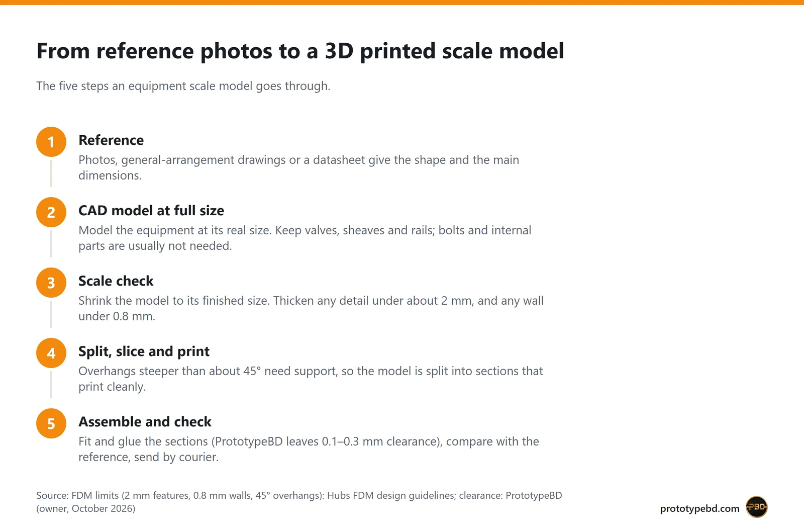
The posts show the start and the end of the job: a CAD model and a finished print. In between, an equipment model like these generally goes through the five steps below.
Reference. Photos, general-arrangement drawings or a manufacturer's datasheet give the overall shape and the main dimensions.
CAD model at full size. The equipment is modelled at its real size first, so every proportion comes from the reference. The details that matter for understanding it, such as valves, sheaves and rails, are kept. Bolts and internal parts usually aren't needed.
Scale check. The model is shrunk to the finished size, and every thin detail is checked again. Fabrication guides for FDM printing list about 2 mm as the smallest reliable feature and 0.8 mm as the thinnest wall (Hubs FDM design guidelines). The scaling is simple division. At 1:50, a 300 mm handwheel becomes 6 mm across, which prints well. A 50 mm valve stem becomes 1 mm, which will snap or disappear. Details like that are thickened in CAD, or you choose a larger scale.
Split, slice and print. Overhangs steeper than about 45° need support material, and pins under about 5 mm in diameter are weak in FDM. Splitting a model into separately printed sections that are glued together afterwards is a normal fix (Hubs: designing parts for FDM). A frame like the choke manifold, with many thin vertical runs and handwheels, benefits from being planned this way.
Assemble and check. The pieces are fitted and glued, the model is compared with the reference, and it is sent by courier. When a handwheel or a pipe run is printed separately and pushed into its socket, PrototypeBD aims for about 0.1 mm of play, and up to 0.3 mm with some materials and printers, so the piece seats fully before it is glued.
Which printers PrototypeBD uses
Palm-sized models like these fit on the Bambu Lab printers that do most of PrototypeBD's work: the P1S, the P2S and the dual-nozzle X2D (Bambu Lab's X2D launch release). Two nozzles let one print carry two colours, which suits a model whose valves or drum are picked out in a second colour. A bigger piece of equipment, such as a full skid on its base, would go on the Creality Ender-5 Max and its 400 × 400 × 400 mm build volume (Creality), so it needs fewer joins. The posts don't say which printer made each of these three models.
FDM or resin?
FDM suits models the size of the three shown here, with chunky shapes and solid colours. If your model has very fine detail, such as thin valve stems, small lettering or a much smaller scale, resin (SLA) printing holds that detail better. The two processes can also be combined, with resin for the small parts and FDM for the frame.
What to send for a quote
If you already have a print-ready file (STL, 3MF or OBJ; STEP and STP files are priced by hand), upload it to the FDM 3D printing quote page. It slices the model and gives you a price for it automatically. If you only have the real equipment to go on, start with the CAD design service and send:
clear photos from several sides, or a general-arrangement drawing;
the main real-world dimensions, such as length, width, height and pipe sizes, if you know them;
the scale you want (for example 1:50) or the finished size, such as "must fit on a 30 cm base";
what the model is for: a desk display, a classroom, an exhibition or a thesis. This decides how much detail is worth modelling;
colours, and whether any lettering or markings need to appear.
If the model is for an exhibition stand, painting in the equipment's real colours, LED lighting and assembly on a base are available on request, and scale figures can also be added on request. None of these is part of a standard print, so mention them when you ask for a quote.
Before you send drawings that belong to an employer or a client, check that you are allowed to share them. Logos and lettering on real equipment belong to their owners, too.
Related articles
Product prototyping with 3D printing: real examples from Bangladesh
Why to prototype before tooling, what form, fit and function prototypes test, and how tight printed fits can be, with eight projects from our Dhaka workshop.
3D Printed Enclosures for Electronics in Bangladesh: Eight Projects and the Design Rules
Eight electronics enclosures PrototypeBD designed or printed, from an IoT gas meter to an MPPT charge controller, and the wall, boss, vent and material rules they show.
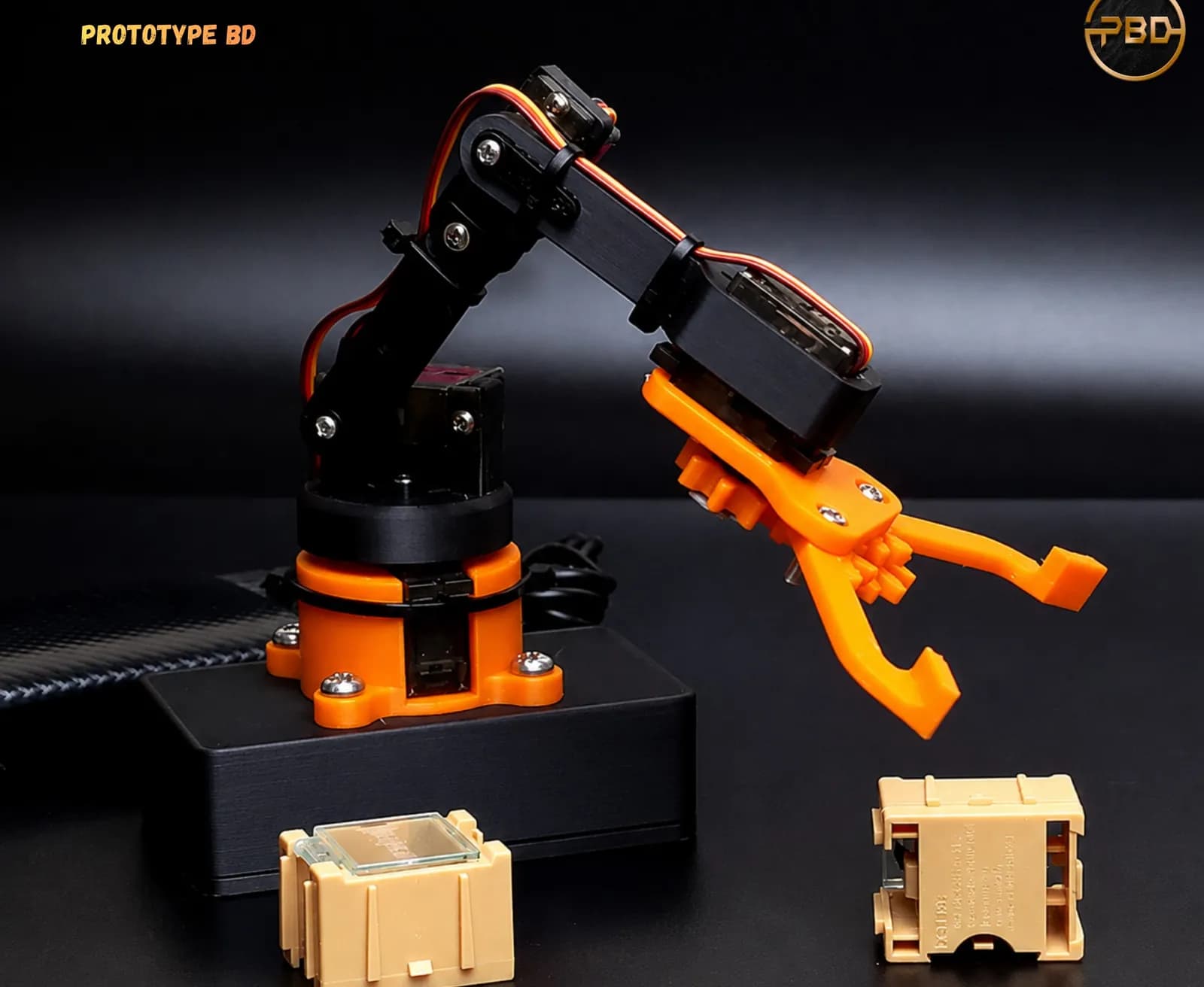
3D Printed Robot Parts in Bangladesh: Six Robotics Projects and a Display Model
What PrototypeBD's robotic arm, rover, self-balancing robot, drone and gear-model prints show about orientation, gears, shafts and filament choice for student robotics.
Comments
Loading comments…