
Crop seeding and cutting machine model on an acrylic base plate
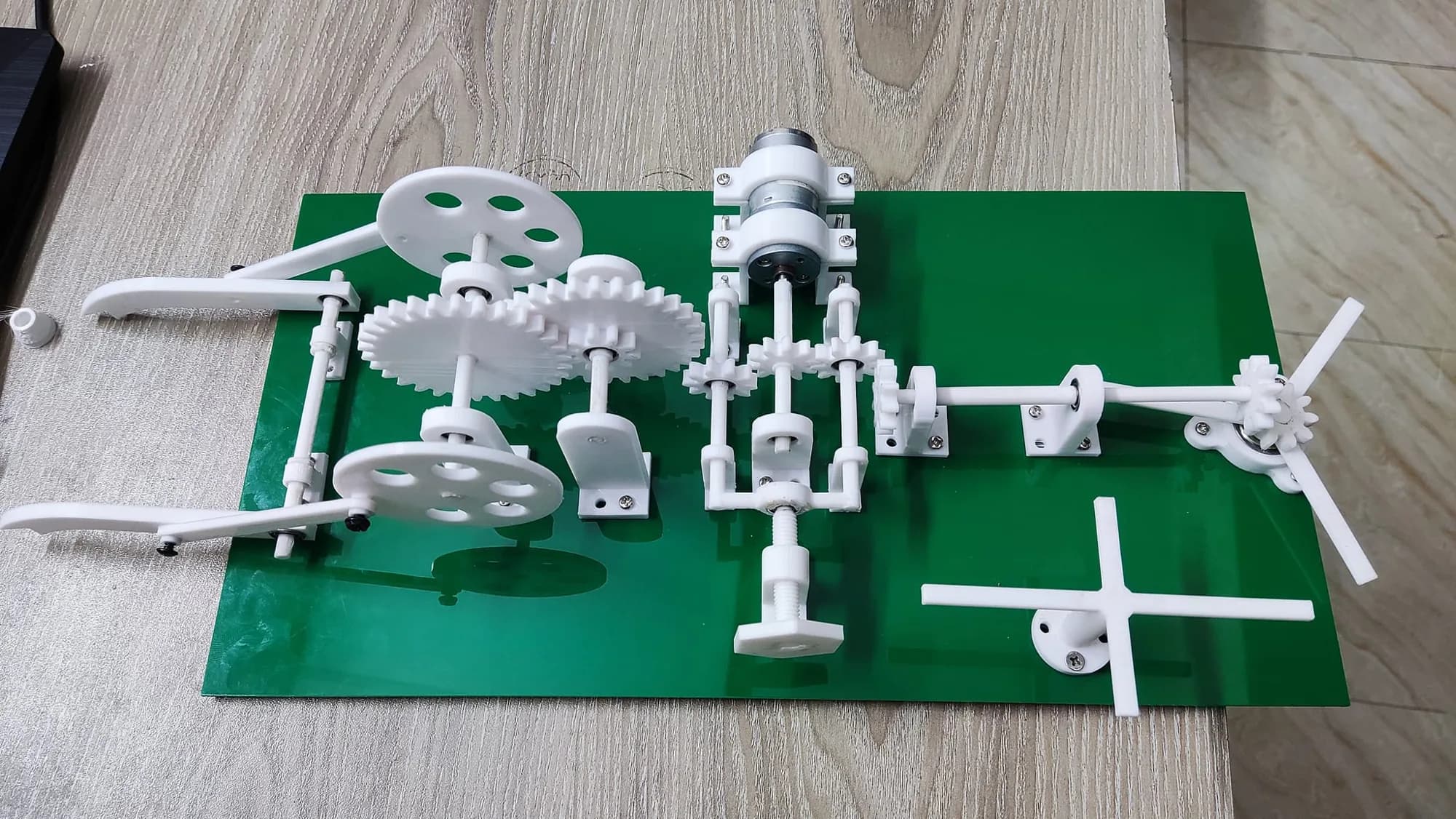
A mechanism model of a crop seeding and cutting machine: 3D printed gears, cranks and bearing blocks with a geared motor, mounted on a green acrylic base plate with a drilled hole pattern. Made with Fusion 360, laser cutting and 3D printing.
- Completed
Specifications
- Type
- Mechanism model (machine concept)
- Design software
- Fusion 360 (as posted)
- Processes (as posted)
- Laser cutting and 3D printing
- Base
- Green acrylic plate with a drilled mounting pattern
- Printed parts
- Gears, pinions, spoked wheels, cranks, bearing blocks, motor clamps
- Drive
- Small geared DC motor (as shown)
- Process
- FDM 3D printing
This model shows the drive train of a crop seeding and cutting machine. The post lists how it was made: designed in Fusion 360, then built with laser cutting and 3D printing, with a KeyShot render for the presentation. It also lists what worked: a new gear-shifting mechanism, workable 3D printed parts and a good use of tolerance.
The base plate
Everything mounts on one green acrylic plate. Before assembly the plate is a flat sheet with a precise pattern of small holes, grouped in fours and twos, one group for each bearing block and bracket. The hole pattern is what puts every shaft in line, so the gears mesh without hand adjustment.
The mechanism
- a small geared DC motor held in printed clamps;
- spur gears and pinions that step the speed down;
- two large spoked wheels with cranks that drive a pair of curved arms;
- a lead screw, a cross-shaped part and a three-blade rotor on separate shafts.
The kit photos show every printed part laid out next to the base plate before assembly.